Related Parts
View More
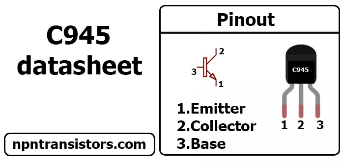
C945 Pinout Universal Shell to PLCC Adapter
The QSP-C179 is a quad-SPAD CMOS image sensor. It is used for various applications like surveillance, robotics, or virtual reality. With this post, we’ll learn about the QSP-C179 pinout and its register settings. The following article explains the working of QSP-C179 in detail. If you are looking for the register settings and datasheet of QSP-C179, you can find it here –
What is a SPAD camera?
SPAD stands for Single Photon Avalanche Diode. It is a photon-counting device used for vision systems. It uses photons to generate electrons at the semiconductor. It is a photodetector that has a very high gain. The SPAD camera is designed for use in low light conditions. That’s why an SPAD camera is also called a photon-counting camera.
QSP-C179 Block Diagram
The block diagram of QSP-C179 is given below. It consists of an Inverse Square Law (ISL) photodetector, an avalanche photodiode (APD), and a CMOS image sensor. The CMOS image sensor is the heart of the system. It converts light into electrical signals. The SPAD of the camera acts as an amplifier to increase the signal. The ISL photodetector is used to measure the light intensity. It generates a photocurrent in the SPAD. The APD of the camera is responsible for detecting the photons. The APD is a semiconductor device that converts the photons into electrons. It generates high current when photons are incident on it. The photodetector of the camera is an integrated circuit that is used to measure the light intensity.
PINOUT of QSP-C179
The camera’s pinout is shown in the below figure. It consists of 8 pins. The camera consists of 6 signal lines and 2 power supply lines. The reset pin is used to reset the camera. The power supply lines are used to provide power to the camera The camera’s data out pin is used to read the image data. The clock pin is used to run the camera
Working of QSP-C179
The camera consists of an APD and an ISL. The ISL produces a photocurrent when the light is incident on it. When the light is incident on the APD, it produces electrons. The camera has 4 layers of semiconductors. The top layer is the photodetector, the second layer is the APD, the third layer is the ISL, and the bottom layer is the CMOS image sensor. The CMOS image sensor converts the light intensity into electrical signals. The ISL is used to amplify the signals. The APD is used to generate electrons due to the photons.
Error Codes in QSP-C179
The camera has 2 error codes – – The camera’s data out pin is low, when the camera is in error state.
Tips to use QSP-C179 effectively
– You should connect and power the camera before applying the reset. – You should enable the camera’s interrupt when you want to read data. – You should disable the camera’s interrupt when you want to reset the camera.
Conclusion
The QSP-C179 is a quad-SPAD CMOS image sensor. The sensor is used for various applications like surveillance, robotics, or virtual reality. The QSP-C179 block diagram, pinout, error codes, and tips to use QSP-C179 effectively are explained above. If you want to use the camera for your project, you can go through the article to learn more about it.