Related Parts
View More

Including Vector Diagram As The Inductor Working Principle
What is an Inductor?
An inductor like Sunlord Fixed Inductor is a passive electrical component that stores energy in a magnetic field when an electric current passes through it. The effects of inductors are seen in everyday life, including the operation of transformers and electric motors.
Inductors are used to block AC voltage, filter DC voltages, and currents, oppose sudden changes in current, store energy temporarily, and more. The types of inductors like TDK Fixed Inductors are also used as antennas in radio systems and as sensors in proximity switches.
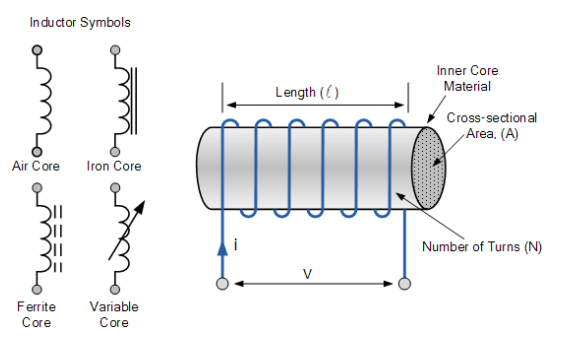
Working Principle of an Inductor
An inductor is a passive electrical component that stores energy in a magnetic field. It is composed of at least one coil of insulated copper wires. In the case of an inductor working principle, the more turns in the coil, the greater the magnetic field it will produce.
The more current that passes through the wire, the greater the magnetic field strength at any point in space around the wire. The strength of this magnetic field is called inductance, and it is measured in units of henries (H).
In an inductor, when current flows through its conductors, a magnetic field is created around them. The direction of this field can be either clockwise or counterclockwise depending on whether current flows into or out of the conductor. This property is called flux linkage (Φ).
The inductor’s ability to store energy in its magnetic field depends on how much current flows through it. If no current flows through an inductor there will be no voltage drop across its leads.
However, if the current does flow there will be a voltage drop across its leads because it takes energy from one path and gives it to another path; hence power loss occurs due to a voltage drop across resistance R.
To understand this better, let’s look at what happens during any given instance when current flows through an inductor:
When current enters one end of an inductor coil (the beginning), it creates a magnetic field around itself because of its conductive properties. The strength of this field increases or decreases depending on how much current flows through the coil.
This is what we’re measuring when we use an ammeter — we’re measuring how much current is flowing through the conductor in question; more current means a stronger magnetic field.
Inductance
Inductance is the property of an electric circuit by which a change in current through it produces a proportional voltage across the circuit, a phenomenon known as self-induction. It is usually defined as the rate of change of flux linkage per unit voltage. Mathematically, this can be expressed as
where λ is the inductance and dΦ/dV is called the ‘slope’ of the curve relating B to V. Inductance is usually measured in mH (millihenries) or H (henries).
Where, L = Inductance
I = Electric Current
V = Voltage
How does an Inductor Work?
Inductors such as Murata Fixed Inductors are passive electrical components that can store energy in a magnetic field. According to the inductor working principle, they are typically used in electronic circuits to block DC current or to filter AC current. This property makes them ideal for use in radio frequency circuits like radio transmitters and receivers, oscillators, and amplifiers.
Inductors are made of wire wound around a core of ferromagnetic material such as iron or steel to form a coil. The high permeability of the core allows it to store energy by creating a magnetic field around the coil which increases with time. With the inductor working principle, the inductor’s self-inductance is proportional to the number of turns n of wire and their distance d apart: L = n² π f * d
The Magnetic Field around a Coil
The magnetic field around a coil is the magnetic field that exists because of the current flowing in the coil. The magnetic field is generated by moving charges, so the force is an example of electromagnetic force. The strength of the magnetic field increases with the increasing current in the coil and decreases with increasing distance from the center of the coil.
As the inductor working principle, the fields around coils are useful for determining whether a body experiences a force when placed within them. A current-carrying wire produces a magnetic field that wraps around it in such a way as to cause an electric field perpendicular to both wires and to the direction of current flow.
If two parallel wires carry currents in opposite directions, then the magnetic fields produced by each wire repel each other so strongly that they are prevented from touching. When two parallel wires carry currents in opposite directions, there will be no net force on them due to their interaction with each other’s electric fields; however, there will be forces on objects placed inside or outside these wires.
The Magnetic Potential Energy in a Magnetic Field of a Coil
The magnetic potential energy in a magnetic field of a coil is the sum of the electric potential energy and the gravitational potential energy.
The electric potential energy is defined by: where q is the charge on the particle, V is the voltage difference across the particle, and r is the distance from the center of mass of the particle to its location.
The gravitational potential energy is defined by: where m is the mass of the particle, g is Newton’s constant times 9.8 N/kg, and h is again r.
Now we consider a closed system consisting of an inductor (an electromagnet) and an iron core that has negligible magnetic properties. The iron core has mass M and radius R. We will assume that there are no electric currents in this system (otherwise we could simply add them to those already present in order to cancel out any net effects).
Conclusion
An inductor is a passive two-terminal electrical component that resists changes in electric current passing through it. It consists of a coil of wire which creates a magnetic field when current flows through it.
An inductor’s opposition to current change is described by the constant called its inductance, and the properties are explained by the physics principle called Faraday’s law of induction.